esp32 시작하기
ESP32 시작하기
Driver 설치: 처음 설치하는 경우
ESP32는 USB-to-Serial bridge로 Silicon Labs의 CP210x를 사용한다. 제조사 홈페이지에서 자신이 사용하는 OS에 알맞는 CP210x 드라이버를 다운받아 설치한다.
1 | https://www.silabs.com/products/development-tools/software/usb-to-uart-bridge-vcp-drivers |
Arduino IDE 설치
1 | https://www.arduino.cc/en/software |
Arduino IDE 설정
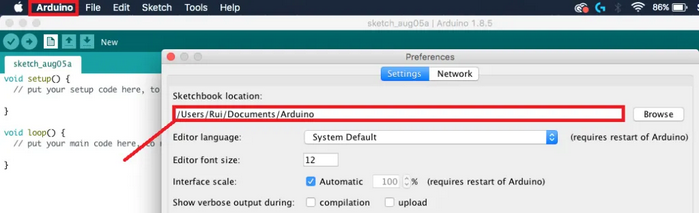
- Arduino IDE에서 파일> 환경설정> 설정 (File> Preferences> Settings)
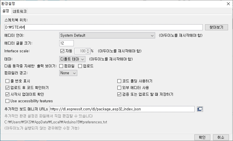
- 추가적인 보드 매니저 URLs에 아래 내용을 추가한다.
1 | https://dl.espressif.com/dl/package_esp32_index.json |
- ESP8266에 대한 URLs를 사용하고 있었다면, comma를 사용하여 구분하면 두가지를 모두 사용할 수 있다.
1 | https://dl.espressif.com/dl/package_esp32_index.json, http://arduino.esp8266.com/stable/package_esp8266com_index.json |
- 툴> 보드> 보드 매니저… Tools> Board> Board Manager…
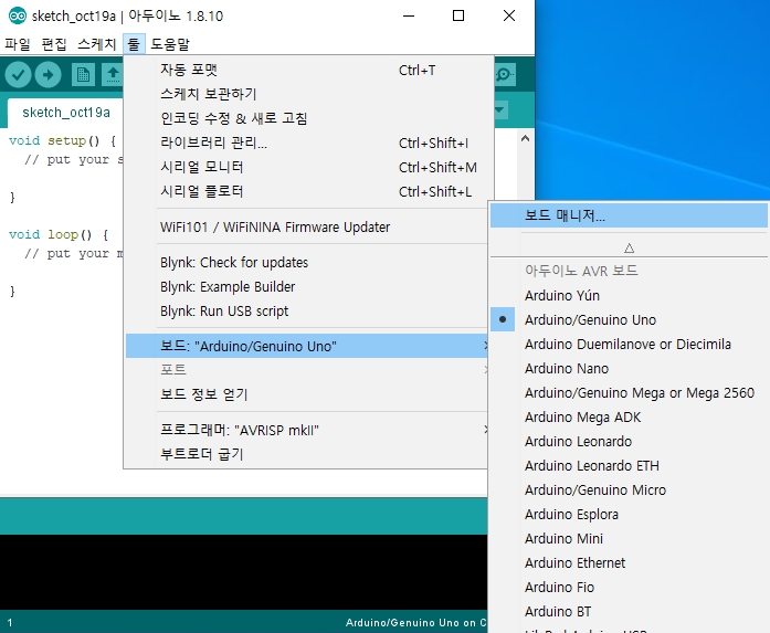
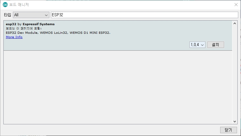
- 보드 매니저에서 “ESP32”를 검색하여 INSTALL (혹은 업데이트)
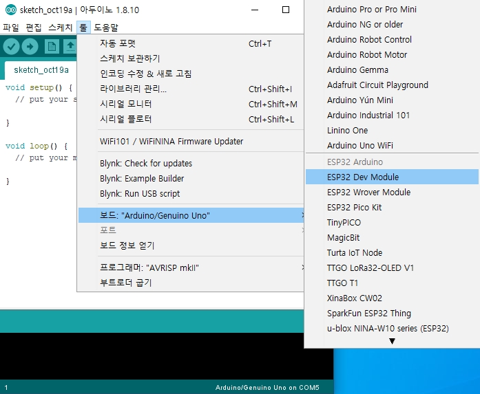
- ESP32를 컴퓨터에 연결한 뒤, 툴> 보드 에서 ESP32 Dev Module 선택
- 툴> 포트 에서 포트 선택 (단, ESP32용 포트가 선택이 되지 않으면 CP210x USB to UART Bridge VCP Drivers를 설치하여야 한다. Windows, Mac 등 사용하고 있는 OS에 적합한 드라이버를 클릭하여 설치한다.
Testing Installation
Example 1. LED Blink
1 | #include <Arduino.h> |
| ESP32 GPIO | 19 | GND |
|---|---|---|
| 저항 | 150Ω | |
| LED | (+)극 | (-)극 |

Upload
스케치 업로드는 아래 3가지 방법 중 하나로 진행할 수 있다.
- 단축키: Ctrl-U
- Sketch> Upload
- 업로드 아이콘 클릭
※ 아두이노에 비해 컴파일 및 업로드 시간이 오래걸림

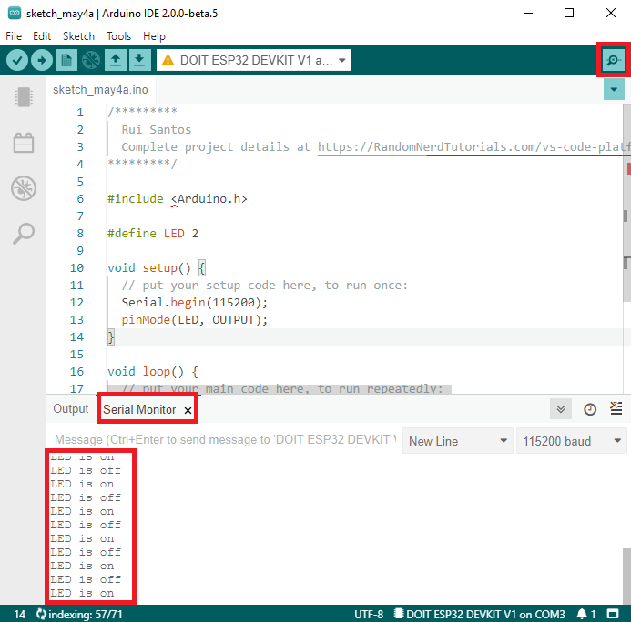
Serial Monitor
Example 2. WiFiScan
예제 선택: 파일 > 예제 > WiFi (ESP32) > WiFiScan
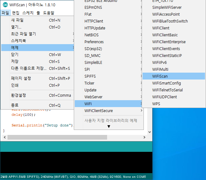
※ 주의: ESP32보드를 연결한 상태에서만 위 예제를 선택할 수 있다.
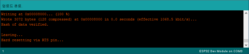
Upload
아두이노에 비하여 업로드 시간이 많이 걸린다. “업로드 완료”라는 메세지가 나타날때까지 잠시 기다린다.
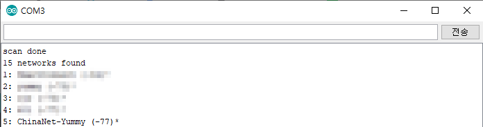
Serial Monitor
아두이노 IDE의 시리얼 모니터를 열고 Baud rate를 115200으로 설정하면 주변의 접속 가능한 WiFi의 SSID가 표시된다. 여기까지 진행이 되면 ESP32가 잘 설치된 것이다.
Troubleshooting
- 업로드시, “A fatal error occurred: Failed to connect to ESP32: Timed out… Connecting…”이라는 메세지가 나오면서 업로드가 진행되지 않는다면, 우선 IDE의 보드와 포트가 알맞게 선택되어 있는지 확인해본다. 그럼에도 문제가 해결되지 않는다면 아래의 방법을 따른다. (※상기 문제가 해결되어 나온 보드의 경우에는 관계없음)
- ESP32 보드에 있는 Boot버튼을 누른채로 업로드 버튼을 클릭하고, Connecting…. 이라는 메세지가 나오면 Boot버튼에서 손가락을 뗀다.
- 일부 ESP32 보드의 경우 새로운 스케치를 업로드 할 때마다 “ENABLE”버튼을 눌러 ESP32를 다시 시작해야 하는 경우도 있는데, 이런 문제가 발생하는 보드의 경우 새 스케치를 업로드 할 때마다 해당 버튼 순서(BOOT-EN)를 반복해야합니다.
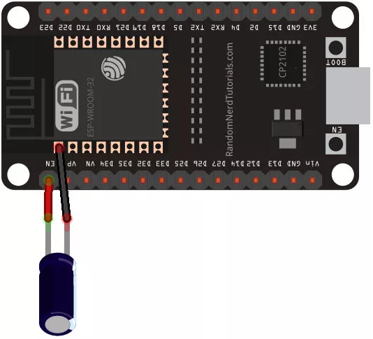
- 이러한 문제를 해결하기 위해서는 ESP32보드의 EN핀과 GND를 10uF 컨덴서를 사용하여 연결해주면 된다.
- Mac OS X & Linux
전체적인 설치방법은 Windows와 동일하다. 단, 첫번째 설치가 아닌 재설치 과정을 수행하는한 경우에는 다음
과정을 통해 espressif폴더를 지운 후 설치과정을 시작하여야 한다.
- Arduino> Preferences> Sketchbook Location에 표기되어 있는 폴더를 복사하여 해당 디렉토리로 진입한 후,
Hardware 폴더 안에 있는 espressif 폴더를 삭제한다.
이후 Windows 설치과정과 유사한 과정을 통해 ESP32를 설치한다.
PWM 제어 방법
원문: https://randomnerdtutorials.com/esp32-pwm-arduino-ide/
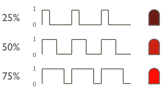
PWM(Pulse Width Modulation) 그림과 같은 주기적인 펄스 신호를 생성하고 1로 되어있는 시간과 0으로되어있는 시간의 비율 (듀티 비)를 바꿈으로써 전송 전력을 변화시킨다.
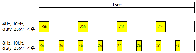
duty 값은 한 주기 내에서 ON 시간과 OFF 시간의 ‘비율’을 결정하는 값이다. PWM 주파수가 다르면 같은 duty 값이라도 ON 되어 있는 시간이 달라진다. 다만 전체적으로 ON 시간의 합과 OFF 시간의 합의 비율은 동일하다.
이런 방법을 LED의 점등에 적용하면, 1의 값을 갖는 시간이 짧을 수록 사람 눈에는 LED가 어둡게 보이고, 1의 값을 갖는 시간이 길 수록 밝아 보이게 된다.
ESP32에서 PWM의 설정
ESP32에는 16 개의 독립적인 채널을 가진 LED PWM 컨트롤러가 있으며 다른 속성으로도 PWM 신호를 생성하도록 구성할 수 있다. Arduino IDE를 사용하여 PWM으로 LED의 밝기를 조절해보도록 한다. 우선 PWM을 사용하기 위해 다음의 4가지를 설정해야 한다.
Channel
0~15까지 16 개의 채널 중 적당한 PWM 채널을 선택한다.
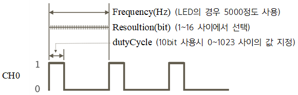
Frequency
PWM 신호 주파수를 설정한다. (LED의 경우 5000Hz의 주파수를 사용)
Resolution
해상도는 output을 위한 값의 범위를 지정하는데 사용하며, 1~16비트 범위에서 선택한다.
- 만약 8비트 해상도를 사용한다면 0~255 사이의 dutyCycle 값을 사용하여 LED 밝기를 제어할 수 있다.
- 10비트를 사용하면 0~1023범위,
- 16비트로 사용한다면 0~65535 범위에서 세밀한 제어를 할 수 있도록 지정된다.
- 참고: 아두이노 우노의 경우, analogWrite()의 해상도는 8비트, 즉 0~255로 고정되어 있다.
GPIO
신호가 표시 될 GPIO를 지정한다.
코드 적용
이러한 설정은 void setup()에서 다음의 코드로 지정한다.
1 | ledcSetup(ledChannel, freq, resolution); // 출력 채널에서 사용할 주파수와 해상도 지정 |
출력 강도는 resolution과 dutyCycle 값으로 결정한다!
- resolution이 8bit이면, 0~255 범위 내에서 dutyCycle을 지정하여 출력강도를 설정하면 됨.
- resolution이 10bit이면, 0~1023 범위 내에서 dutyCycle을 지정하여 출력강도를 설정하면 됨.
- resolution이 16bit이면, 0~65535 범위 내에서 dutyCycle을 지정하여 출력강도를 설정하면 됨.
LED Dimming
schematic
sketch
1 | // the number of the Red LED pin |
RGB LED Dimming
같은 channel에 있는 3개의 서로 다른 GPIO에는 같은 값의 signal을 줄 수 있다.
schematic

sketch
1 | // the number of the 3 LED pin |