DC모터 + 4WD 자동차 만들기 (TB6612FNG)
DC모터 사용하기
아두이노의 5V, 3.3V핀으로는 모터에 필요한 충분한 전압과 전류를 공급하기 어렵다. 그러므로 사용하려는 모터에 맞는 전압과 전류의 공급을 위한 모터드라이버를 사용해야 한다. 아두이노에서 주로 사용하는 모듈은 L293D, L298N와 TB6612FNG 등이 있으며, 여기서는 TB6612FNG 모터드라이버와 함께, 모터 및 아두이노 단독사용을 위하여 별도의 외부전원을 사용한다. 외부 전원으로는 모터를 위한 1.5V AA*4개와 함께 아두이노 단독사용을 위한 9V 사각전지(6F22)를 추가로 연결하였다.
1.5V AA 6개 혹은 3.7V 18650 2개를 직렬로 연결하여 사용하면, 9V 사각전지(6F22)가 필요하지 않으므로 이 방법을 추천한다. 또한 AA 건전지를 사용하는 경우 4WD기준 연속사용시간은 10분 정도뿐일 정도로 전지 소모가 매우 빠르므로, 충전이 가능한 18650 사용을 추천한다.
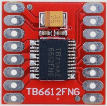
TB6612FNG
| VM VCC GND(*) AOUT1 AOUT2 BOUT2 BOUT1 GND |
 |
PWMA AIN2 AIN1 STBY BIN1 BIN2 PWMB GND |
|---|---|---|
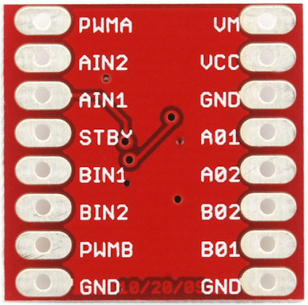 |
- VM (모터 전압) = 15V max
- VCC (로직 전압) = 2.7 ~ 5.5V
- GND
- TB6612fng 모듈을 여러개 테스트한 결과, 3번핀 GND에 연결할 경우 작동이 안되는 몇몇 제품이 있었음
- 그러므로 8번핀, 9번핀의 GND 사용을 권장함
- 출력전류: 정전류 1.2A (3.2A peak)까지 (모터 2개 사용시 합산 전류임)
- 모터 제어모드: CW, CCW, short-brake, STOP, stand-by
- 두개의 모터 출력을 개별 제어하며, 100kHz의 PWM으로 속도 제어
- 써멀 셧다운 및 저전압 감지회로 내장
Pin의 사용
| 핀번호 | 모터드라이브1 | 아두이노 | 외부전원 | 모터 / 역할 |
|---|---|---|---|---|
| 1 | VM | (+) (DC모터에 사용하는 전압 사용) | ||
| 2 | VCC | +5V | ||
| 3 | GND (사용 비추천) | |||
| 4 | A_OUT1 | 모터A | ||
| 5 | A_OUT2 | 모터A | ||
| 6 | B_OUT2 | 모터B | ||
| 7 | B_OUT1 | 모터B | ||
| 8 | GND | (-) | ||
| 9 | GND | GND | ||
| 10 | B_PWM | 6 | 모터B 속도제어 | |
| 11 | B_IN2 | 12 | 모터B 방향제어 | |
| 12 | B_IN1 | 11 | 모터B 방향제어 | |
| 13 | STBY | 10 | 모터 상태신호 | |
| 14 | A_IN1 | 9 | 모터A 방향제어 | |
| 15 | A_IN2 | 8 | 모터A 방향제어 | |
| 16 | A_PWM | 5 | 모터A 속도제어 |
- 속도제어에 사용하는 A_PWM, B_PWM은 아두이노의 PWM이 가능한 핀에 연결하여야 합니다. 여기서는 ~5, ~6번 핀 사용.
주의: Pin Map이 다른 모듈의 경우
TB6612FNG를 여러 개 구입하여 사용해본 결과, 위의 핀맵과 조금 다른 모듈도 있었다.
| 핀번호 | 모터드라이브1 | 아두이노 | 외부전원 | 모터 / 역할 |
|---|---|---|---|---|
| 1 | GND | GND | (-) | |
| 2 | VCC (2.7~5.5V) | +5V | ||
| 3 | A_OUT1 | 모터A | ||
| 4 | A_OUT2 | 모터A | ||
| 5 | B_OUT2 | 모터B | ||
| 6 | B_OUT1 | 모터B | ||
| 7 | VM (15V max) | (+) (DC모터 요구 전압 사용) | ||
| 8 | GND | |||
| 9 | GND | |||
| 10 | B_PWM | 6 | 모터B 속도제어 | |
| 11 | B_IN2 | 12 | 모터B 방향제어 | |
| 12 | B_IN1 | 11 | 모터B 방향제어 | |
| 13 | NC(STBY) | 10 | 모터 상태신호 | |
| 14 | A_IN1 | 9 | 모터A 방향제어 | |
| 15 | A_IN2 | 8 | 모터A 방향제어 | |
| 16 | A_PWM | 5 | 모터A 속도제어 |
TB6612FNG와 DC모터의 연결
Pin Map
TB6612FNG 모터드라이브는 2채널 형태이며, 만일 2WD 자동차를 만든다면 디지털핀 7개가 필요하다. 4개의 DC모터를 사용하여 4WD 자동차를 만드는 방법은 3가지로 나눠 생각해볼 수 있는데, 모든 바퀴를 각각 컨트롤 하는 방법, 왼쪽 바퀴와 오른쪽 바퀴로 나누어 컨트롤 하는 방법, 앞 바퀴와 뒷 바퀴로 나누어 컨트롤 하는 방법 등이 있다.
- 모든 바퀴를 각각 컨트롤 하는 경우 : 모터드라이브 2개와 디지털핀 14개 사용
- 그런데, 아두이노에서 실제 사용할 수 있는 디지털핀의 개수가 12개(2~13번)이므로, 2개의 디지털핀이 부족하다.
- 아날로그핀을 디지털핀과 동일하게 사용할 수 있으므로, 2개의 아날로그핀을 추가로 사용한다.
- 또는 스케치 업로드시에만 0,1번 핀을 빼두었다가, 스케치 업로드가 끝나면 0,1번 핀을 사용한다. 이렇게 사용하면 0~13번까지 총 14개의 디지털핀을 확보할 수 있다.
- 그런데, 아두이노에서 실제 사용할 수 있는 디지털핀의 개수가 12개(2~13번)이므로, 2개의 디지털핀이 부족하다.
- 왼쪽과 오른쪽 바퀴로 나누어 컨트롤 하는 방법 : 디지털핀 7개 사용 (아래 본문에서 사용한 방법)
- 앞과 뒷 바퀴로 나누어 컨트롤 하는 방법 : 디지털핀 7개 사용. (단, 조향을 위한 추가적인 방법을 고려해야 함.)
H-SW Control Function
| Input | Output | |||||
|---|---|---|---|---|---|---|
| IN1 | IN2 | PWM | STBY | OUT1 | OUT2 | Mode |
| H | H | H/L | H | L | L | Short Brake |
| L | H | H | H | L | H | Count-Clockwise |
| L | H | L | H | L | L | Short Brake |
| H | L | H | H | H | L | Clockwise |
| H | L | L | H | L | L | Short Brake |
| L | L | H | H | OFF(High impedance) | OFF(High impedance) | Stop |
| H/L | H/L | H/L | L | OFF(High impedance) | OFF(High impedance) | Standby |
출력 결과는 아래와 같으며,
- IN1이 LOW, IN2가 HIGH, PWM으로 신호를 출력할 경우 시계 반대 방향(CCW)으로 회전
- IN1이 HIGH, IN2가 LOW, PWM으로 신호를 출력할 경우 시계 방향(CW)으로 회전
- 그 밖의 경우는 모두 stop 상태로 해석하면 된다.
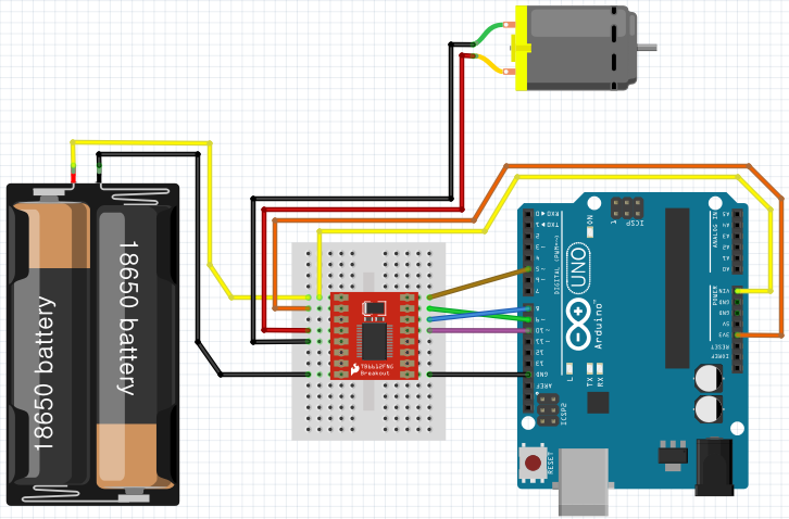
모터 1개 컨트롤하기
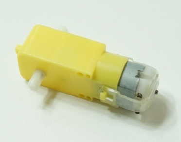
여기서 사용하는 DC모터는 아래의 형태를 가진 기어드모터이며, 아두이노를 사용하여 자동차를 만드는데 많이 사용되는 저렴이 모터이다.
schematic
UNO보드와 컴퓨터를 USB선으로 연결하여 사용할 경우
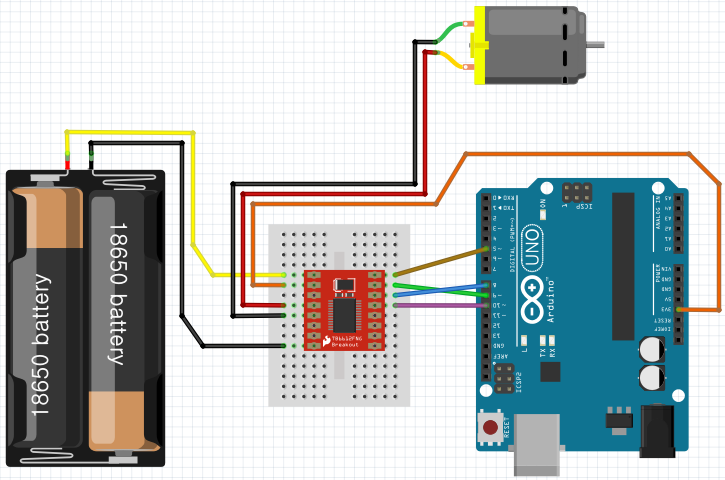
UNO보드와 컴퓨터의 연결없이 Vin핀을 사용하여 단독으로 사용할 경우
- UNO 보드의 Vin에 외부전원(7.4V) (+)에 연결: 6.6V~12V 범위의 전원 연결 가능 (7.2V 이상 추천)
- UNO 보드의 GND를 TB6612fng 모듈의 GND에 연결
sketch
1 | int STBY = 10; // Standby |
회전 방향이 (생각했던 방향과) 반대로 회전하는 경우
A_IN1핀과 A_IN2 핀의 번호를 바꿔준다. 즉, 위 스케치에서
1 | int A_IN1 = 8; |
부분을
1 | int A_IN1 = 9; |
로 바꿔준다.
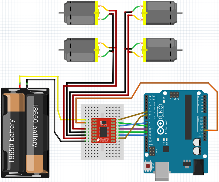
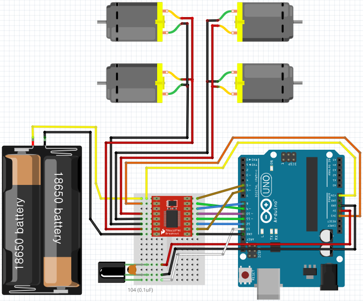
4WD 자동차 만들기
schematic
UNO보드와 컴퓨터를 USB선으로 연결하여 사용할 경우
UNO보드와 컴퓨터의 연결없이 Vin핀을 사용하여 단독으로 사용할 경우
- UNO 보드의 Vin에 외부전원(7.4V) (+)에 연결: 6.6V~12V 범위의 전원 연결 가능 (7.2V 이상 추천)
- UNO 보드의 GND를 TB6612fng 모듈의 GND에 연결
sketch
1 | // front wheel : B1 - A1 |
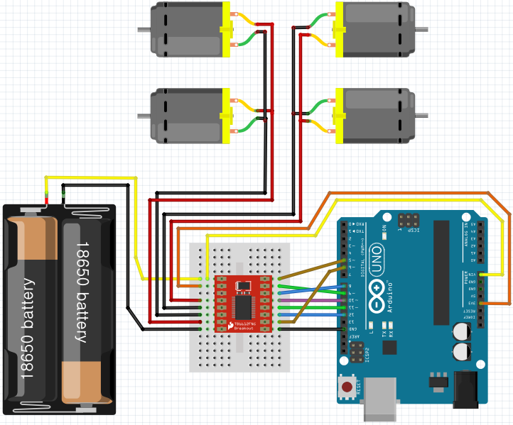
IR 리모컨으로 4WD 컨트롤하기
IR리모컨을 사용하여 RC카를 컨트롤 하기 위해서는 모터와 회로에서 발생하는 노이즈를 제거하기 위한 104 케패시터(0.1uF)를 사용하는 것이 원칙입니다. 반드시 사용해야 하는 것은 아니지만, 회로보호를 위해 캐패시터가 있는 경우에는 IR 수신부의 (+)와 (-)에 병렬연결하세요. 이에 더하여 후진시 방향전환도 가능하도록 수정해 봅니다.
schematic
UNO보드와 컴퓨터를 USB선으로 연결하여 사용할 경우
UNO보드와 컴퓨터의 연결없이 Vin핀을 사용하여 단독으로 사용할 경우
IRremote 라이브러리 추가하기
1 |
사용할 리모컨 버튼 HEX값
| Remote Button | unsigned int data | define |
|---|---|---|
| ▲ (전진 / 속도 증가) | 0XFF18E7 | BTN_U |
| ▼ (후진 / 속도 감소) | 0XFFA4B5 | BTN_D |
| ◀ (좌회전 / 좌회전각 증가) | 0XFF10EF | BTN_L |
| ▶ (우회전 / 우회전각 증가) | 0XFF5AA5 | BTN_R |
| OK (정지) | 0XFF38C7 | BTN_O |
보유하고 있는 리모컨의 종류마다 HEX값이 다르므로, HEX값은 다를 수 있습니다. HEX값을 알아내는 방법은 IR Remote를 다루는 페이지를 참고하세요.
sketch
1 | //Initialize IR remote |
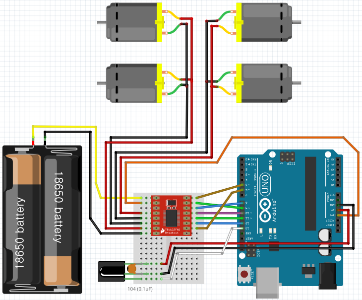
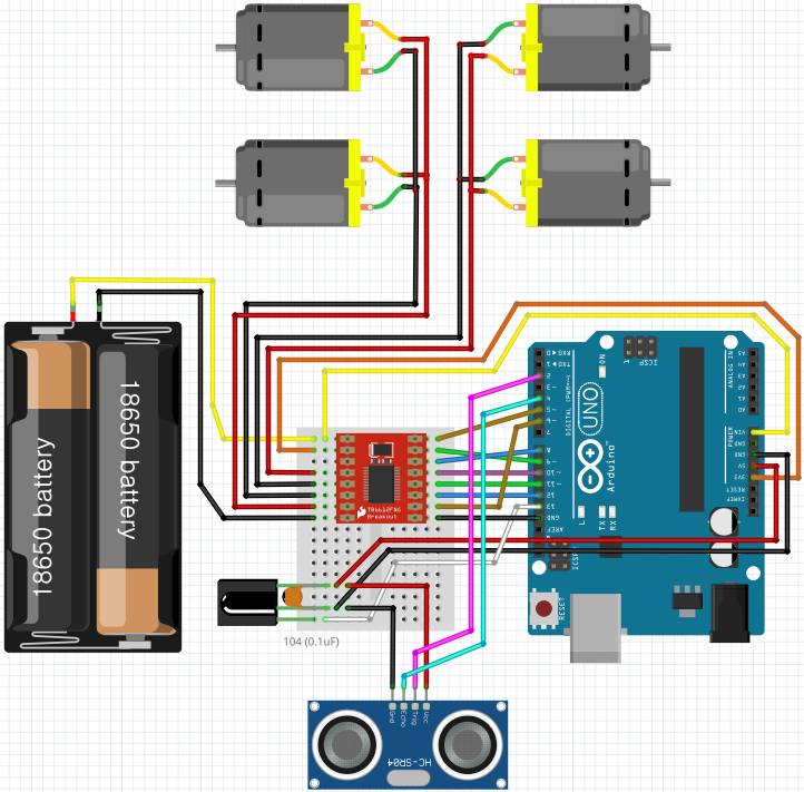
초음파 센서 장착
초음파 센서를 장착하여 전진시 일정한 거리 내에 장애물이 있으면 자동차를 멈춰보도록 하겠습니다. Trig는 아두이노 2번핀, Echo는 4번핀에 연결하였습니다.
schematic
UNO보드와 컴퓨터를 USB선으로 연결하여 사용할 경우

UNO보드와 컴퓨터의 연결없이 Vin핀을 사용하여 단독으로 사용할 경우
sketch
1 | //Initialize IR remote |
DC모터 + 4WD 자동차 만들기 (TB6612FNG)