#include<Stepper.h>// 2048:한바퀴(360도), 1024:반바퀴(180도)...
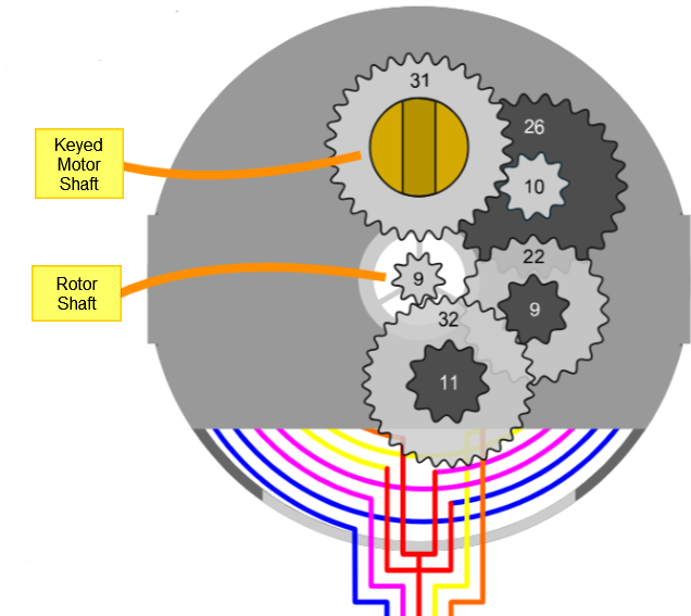
// datasheet를 통해 스트라이드 각도를 계산한 값을 사용
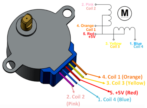
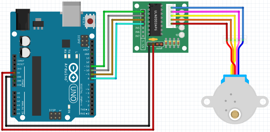
constintstepsPerRevolution=2048;// 모터 드라이브에 연결된 핀 IN1, IN3, IN2, IN4
SteppermyStepper(stepsPerRevolution,11,9,10,8);voidsetup(){myStepper.setSpeed(14);}voidloop(){// 시계 반대 방향으로 한바퀴 회전
myStepper.step(stepsPerRevolution);delay(500);// 시계 방향으로 한바퀴 회전
myStepper.step(-stepsPerRevolution);delay(500);}
#include<Stepper.h>// 2048:한바퀴(360도), 1024:반바퀴(180도), 64:11.25도
constintstepsPerRevolution=64;// 모터 드라이브에 연결된 핀 IN1, IN3, IN2, IN4
SteppermyStepper(stepsPerRevolution,11,9,10,8);voidsetup(){myStepper.setSpeed(16);}voidloop(){// 시계 반대 방향으로 한바퀴 회전
// 64 * 32 = 2048 한바퀴 => 11.25도씩 32번 회전 (360도)
for(inti=0;i<32;i++){myStepper.step(stepsPerRevolution);}delay(500);// 시계 방향으로 한바퀴 회전
// -64 * 32 = 2048 한바퀴 => -11.25도씩 32번 회전 (-360도)
for(inti=0;i<32;i++){myStepper.step(-stepsPerRevolution);}delay(500);}
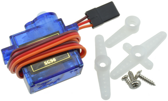
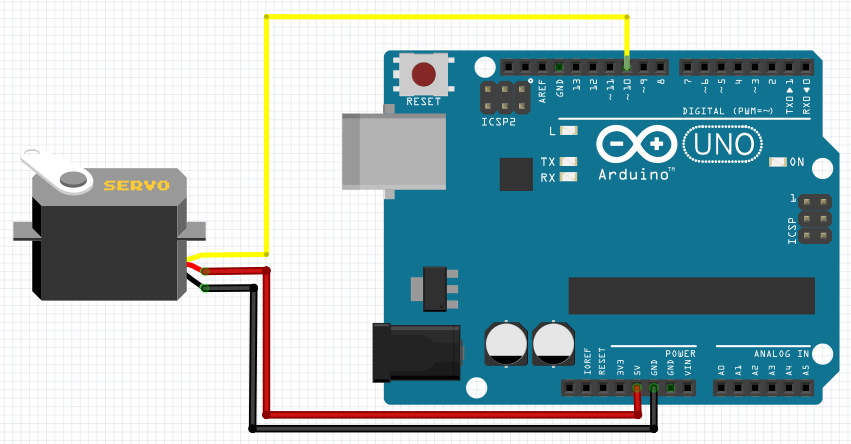
#include<Servo.h>Servoservomotor;// servomotor 선언
intposition=0;voidsetup(){servomotor.attach(10);// servomotor 핀 설정
}voidloop(){for(position=0;position<180;position++){servomotor.write(position);// pos값의 위치로 이동
delay(15);}for(position=180;position>0;position--)// 같은 방법으로 역회전
{servomotor.write(position);delay(15);}}
servomotor.write(숫자)를 사용할때, 숫자는 현재 위치에서의 ‘회전각’을 의미하는 것이 아니다!
초기 위치를 0º로 기준삼아, 표시된 숫자의 각도 위치로 이동하라는 의미이다. 예를들어서 servomotor.write(90)와 servomotor.write(30)을 연속으로 실행하면,
90도를 회전한 뒤, 추가로 30도를 회전하여 120도 위치에 있다 → ×
90도의 위치로 회전한 뒤, 역회전하여 (처음위치를 기준으로) 30도의 위치로 이동한다. → ○
단, servo.h 라이브러리를 사용하면, 스케치 내에서 analogWrite를 사용할 수 없다는 단점도 있다.
#include<Servo.h>Servoservomotor;inta=0;voidsetup(){servomotor.attach(10);Serial.begin(9600);// Serial 통신을 설정
while(!Serial);Serial.println("Servor Mortor");}voidloop(){if(Serial.available()){// Serial 모니터창에 어떤 값이 들어오면 실행
a=Serial.parseInt();// Serial 모니터창에서 받은 값을 a에 넘겨줌
if(a>=0&&a<=180){Serial.print("angle : ");Serial.println(a);servomotor.write(a);// a값에 해당하는 각도의 위치로 이동
delay(15);}}}
Its range is 544-2450 micro seconds for 0-180 degree angle.
Again its a little complex.
For example 0 degree signal will be something like 5 volts for 544 micro seconds and 0 volt for 19465.
highDelay
the time in which we want to keep voltage high on pin 10 and this unit is in micro seconds.
lowDelay
the time in which want to keep voltage zero across pin 10 again this unit is going to be in micro seconds
only HIGH part of signal wont operate servo. we have to send complete HIGH and LOW signal to make servo work.
deg_factor
signal range (2450 - 544) for SG90 divided by 180 which is equal to 10.6 something that we make 11 as an integer.
Loop = 20000;
20000 micro seconds or 20 milli seconds is signal cycle or u can say total signal should be equal to 20 milli seconds including HIGH and LOW input. (50Hz)
intservoPin=10;// servo is connected to pin 10.
intinitialDelay=544;inthighDelay,lowDelay;intdeg;intdeg_factor=10;intLoop=20000;voidsetup(){pinMode(servoPin,OUTPUT);}voidloop(){for(deg=0;deg<=180;deg++){servoWrite(servoPin,deg);}for(deg=180;deg>=0;deg--){servoWrite(servoPin,deg);}}voidservoWrite(intservo,intduty){highDelay=initialDelay+(duty*deg_factor);// setting angle
digitalWrite(servo,HIGH);delayMicroseconds(highDelay);lowDelay=Loop-highDelay;digitalWrite(servo,LOW);delayMicroseconds(lowDelay);delay(500);}
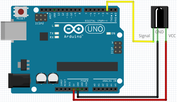
아두이노 학습용으로 판매하는 IR 리시버는 브레드보드에 바로 붙일 수 있도록 조그만 PCB가 달린 모듈의 형태로 판매되는 경우가 많으며, 이 경우에는 PCB보드에 써있는 글씨를 보고 각 핀에 맞게 아두이노에 연결해야한다. 문제는 PCB에 어느 핀인지를 나타내는 글자가 잘 안보인다는 것!
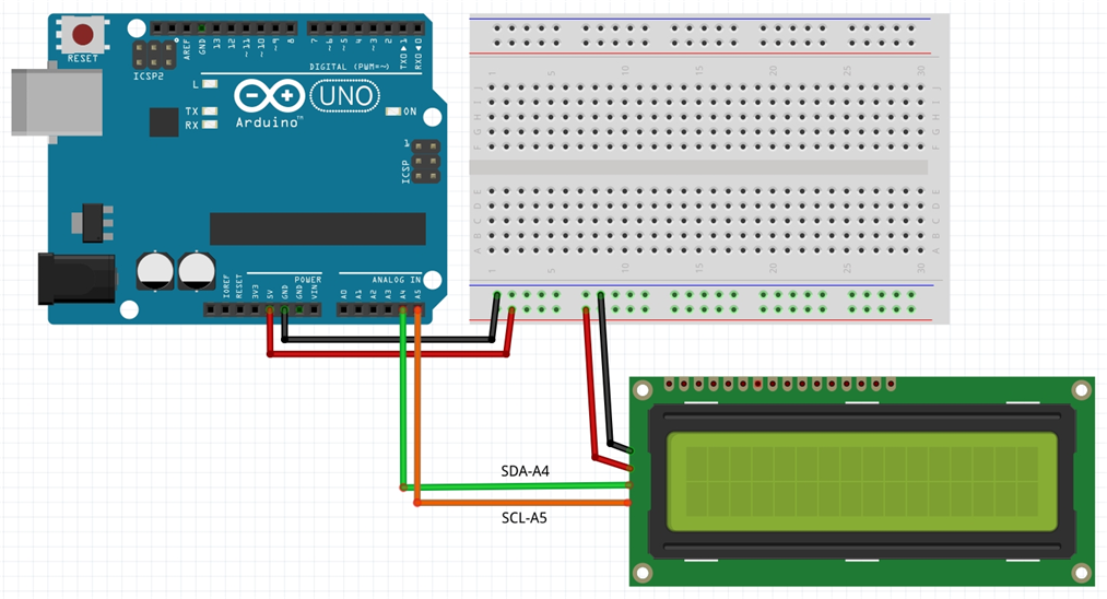
// I2C 1602 LCD (연결핀을 바꿀 수 없음)
// VCC-5V / GND-GND / SDA-A4 / SCL-A5
#include<Wire.h>#include<LiquidCrystal_I2C.h>// i2c address 는 칩에 따라 0x20~0x27 혹은 0x3F값을 가짐
LiquidCrystal_I2Clcd(0x27,16,2);voidsetup(){lcd.init();// lcd 초기화
lcd.backlight();lcd.print("I Love Steam!!");// LCD창에 메시지 출력
delay(1000);}voidloop(){// 문자열의 길이 13개를 왼쪽으로 스크롤
for(intpCount=0;pCount<13;pCount++){lcd.scrollDisplayLeft();// 왼쪽으로 스크롤
delay(700);}// 문자열 길이 13열 + 기본 16열 = 29개 위치를 오른쪽으로 스크롤
for(intpCount=0;pCount<29;pCount++){lcd.scrollDisplayRight();// 오른쪽으로 스크롤
delay(700);}// 왼쪽으로 16개 위치 스크롤하여 처음 위치로 이동
for(intpCount=0;pCount<16;pCount++){lcd.scrollDisplayLeft();// 왼쪽으로 스크롤
delay(700);}delay(1000);}
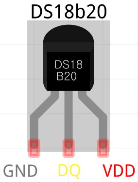
// DS18b20 Temperature Sensor
#include<OneWire.h>#include<DallasTemperature.h>#define TEMP_PIN 2
OneWireoneWire(TEMP_PIN);DallasTemperaturesensors(&oneWire);floatcelciusTemperature;// I2C 1602 LCD (연결핀을 바꿀 수 없음)
// VCC-5V / GND-GND / SDA-A4 / SCL-A5
#include<Wire.h>#include<LiquidCrystal_I2C.h>// i2c address 는 칩에 따라 0x27, 0x3F값을 가짐
LiquidCrystal_I2Clcd(0x27,16,2);voidsetup(){Serial.begin(9600);Serial.println("DallasTemperature IC Control");// Start up the Temperature Sensor library
sensors.begin();// lcd 초기화
lcd.init();lcd.backlight();}voidloop(){sensors.requestTemperatures();celciusTemperature=sensors.getTempCByIndex(0);Serial.print("Temperature is: ");Serial.println(celciusTemperature);lcd.setCursor(0,0);lcd.print("Temperature : ");lcd.setCursor(0,1);lcd.print(celciusTemperature);lcd.print("*C");delay(2000);}
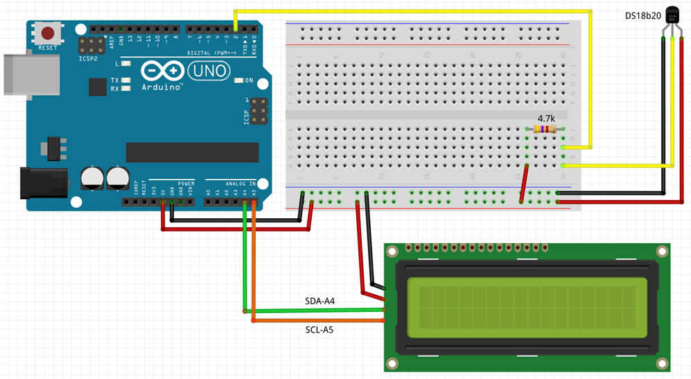
DS18b20 센서는 두 가지 연결방법을 제공하는데, 하나는 VCC를 5V에 연결하는 Normal Mode이고 다른 하나는 VCC를 GND에 연결하는 Parasite Mode이다. 두가지 방법 모두 지원되지만 (경험상) Normal를 추천하며 (원인은 잘 모르겠지만) Parasite Mode에서는 온도센서가 작동이 되지 않는 경우도 가끔 있었다. 회로 구성을 위해 4.7㏀ 저항 1개가 필요하며 Normal Mode 구성을 위해 다음 그림과 같이 연결한다.
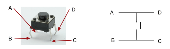
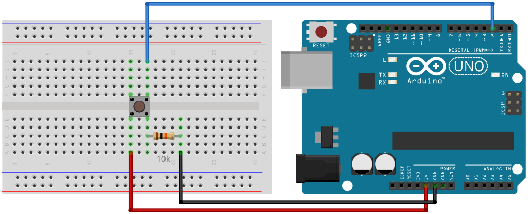
constintswitch_R=2;voidsetup(){pinMode(switch_R,INPUT);Serial.begin(9600);}voidloop(){inti=digitalRead(switch_R);if(i==HIGH){// 스위치를 누르면
Serial.println("1");}else{// 스위치에서 손을 떼면
Serial.println("0");}}
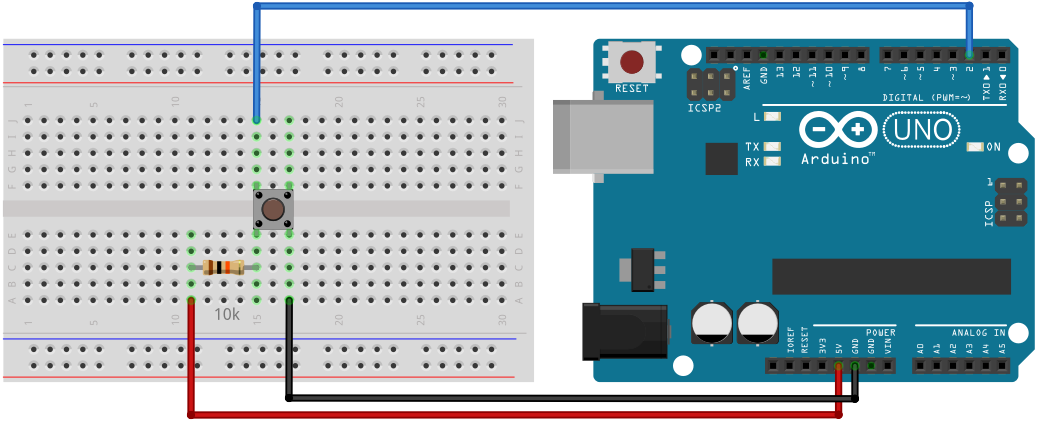
constintswitch_R=2;voidsetup(){pinMode(switch_R,INPUT);Serial.begin(9600);}voidloop(){inti=digitalRead(switch_R);if(i==HIGH){// 스위치를 누르면
Serial.println("1");}else{// 스위치에서 손을 떼면
Serial.println("0");}}