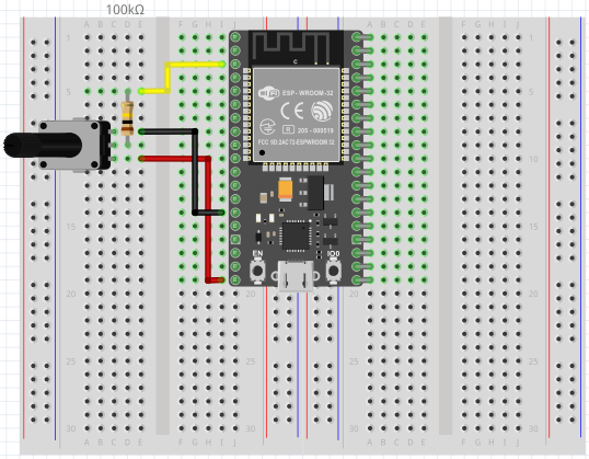
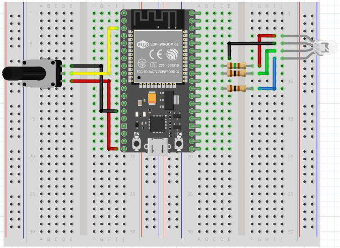
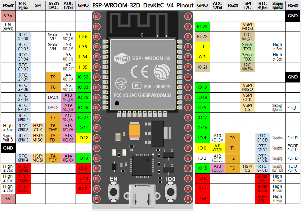
가변저항의 저항을 A0(ADC1_CH0, GPIO36)로 읽고 전압값으로 변환한 뒤 시리얼 모니터로 출력한다.
// ESP32 ADC test
#define analogPin A0
voidsetup(){Serial.begin(115200);}voidloop(){// read the input on analog pin GPIO36 (ADC1_CH0):
intsensorValue=analogRead(analogPin);// Convert the analog (12bit ADC : 0 - 4095) to a voltage (0 - 3.3V):
floatvoltage=(sensorValue/4095.0)*3.3;// print out the value you read:
Serial.println(voltage);delay(200);}
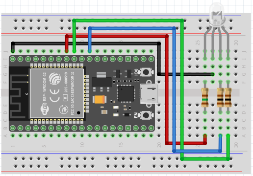
#include <Arduino.h>

const int R_ledPin = 19;

void setup() {
  // put your setup code here, to run once:
  Serial.begin(115200);
  pinMode(R_ledPin, OUTPUT);
}

void loop() {
  // put your main code here, to run repeatedly:
  digitalWrite(R_ledPin, HIGH);
  Serial.println("LED is on");
  delay(1000);
  digitalWrite(R_ledPin, LOW);
  Serial.println("LED is off");
  delay(1000);
}
ADC와 DAC 기능은 특정 핀에 고정되어 있다. 하지만 UART, I2C, SPI, PWM등의 기능은 어느 핀에 사용할지 결정해서 코드에서 지정해 줘야 한다. 소프트웨어에서 핀의 속성을 정의해 줄 수 있지만, 각 핀들은 디폴트로 지정되어 있는 기능들이 있다. (Pinout 참고)