DC모터 사용하기#
아두이노의 경우와 마찬가지로 ESP32에서도 TB6612FNG 모터드라이버와 함께, 모터 및 아두이노 단독사용을 위하여 3.7V 18650 2개를 직렬로 연결한 외부전원을 사용한다.
TB6612FNG#
기본 핀 배열#
| VM VCC GND(*) AOUT1 AOUT2 BOUT2 BOUT1 GND | 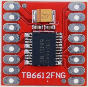 | PWMA AIN2 AIN1 STBY BIN1 BIN2 PWMB GND |
|---|---|---|
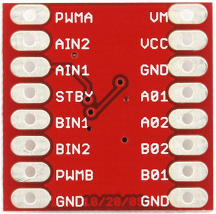 |
핀 배열이 다른 경우#
| GND VCC AOUT1 AOUT2 BOUT2 BOUT1 VM GND | 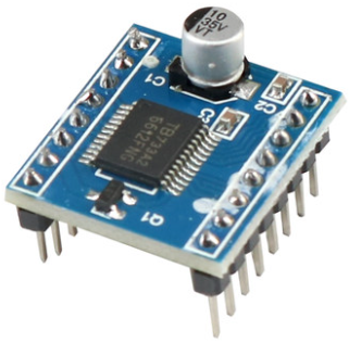 | PWMA AIN2 AIN1 NC (=STBY) BIN1 BIN2 PWMB GND |
|---|---|---|
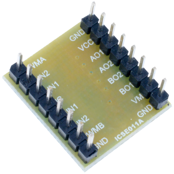 |
- VM (모터 전압) = 15V max
- VCC (로직 전압) = 2.7 ~ 5.5V
- GND
- TB6612FNG 모듈을 여러개 테스트한 결과, 기본 핀 배열을 가진 모듈의 3번핀 GND에 연결할 경우 작동이 안되는 몇몇 제품이 있었음
- 그러므로 8번핀, 9번핀의 GND 사용을 권장함
- 출력전류: 정전류 1.2A (3.2A peak)까지 (모터 2개 사용시 합산 전류임)
- 모터 제어모드: CW, CCW, short-brake, STOP, stand-by
- 두개의 모터 출력을 개별 제어하며, 100kHz의 PWM으로 속도 제어
- 써멀 셧다운 및 저전압 감지회로 내장
Pin의 사용#
ESP32와 TB6612FNG모듈을 브레드보드를 통해 연결하기 쉽도록 핀을 구성한 Pinmap이므로, 필요에 따라 수정하여 사용할 수 있다. (아래표는 참고만 할 것!)
| 핀번호 | TB6612FNG 모터드라이브 (기본 핀 배열) | ESP32 DEVKIT_C V4 사용시 | ESP32 DEVKIT V1 사용시 | 외부전원 | 모터 / 역할 |
|---|---|---|---|---|---|
| 1 | VM | (+) (DC모터에 사용하는 전압 사용) | |||
| 2 | VCC | +3.3V | +3.3V | ||
| 3 | GND (사용 비추천) | ||||
| 4 | A_OUT1 | 모터A | |||
| 5 | A_OUT2 | 모터A | |||
| 6 | B_OUT2 | 모터B | |||
| 7 | B_OUT1 | 모터B | |||
| 8 | GND | (-) | |||
| 9 | GND | GND | GND | ||
| 10 | B_PWM | 12 | 13 | 모터B 속도제어 | |
| 11 | B_IN2 | 14 | 12 | 모터B 방향제어 | |
| 12 | B_IN1 | 27 | 14 | 모터B 방향제어 | |
| 13 | STBY | 26 | 27 | 모터 상태신호 | |
| 14 | A_IN1 | 25 | 26 | 모터A 방향제어 | |
| 15 | A_IN2 | 33 | 25 | 모터A 방향제어 | |
| 16 | A_PWM | 32 | 33 | 모터A 속도제어 |
| ESP32 DEVKIT V4 사용시 | 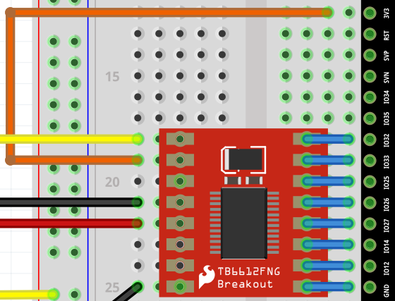 |
|---|---|
| ESP32 DEVKIT V1 사용시 | 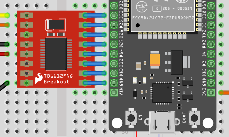 |
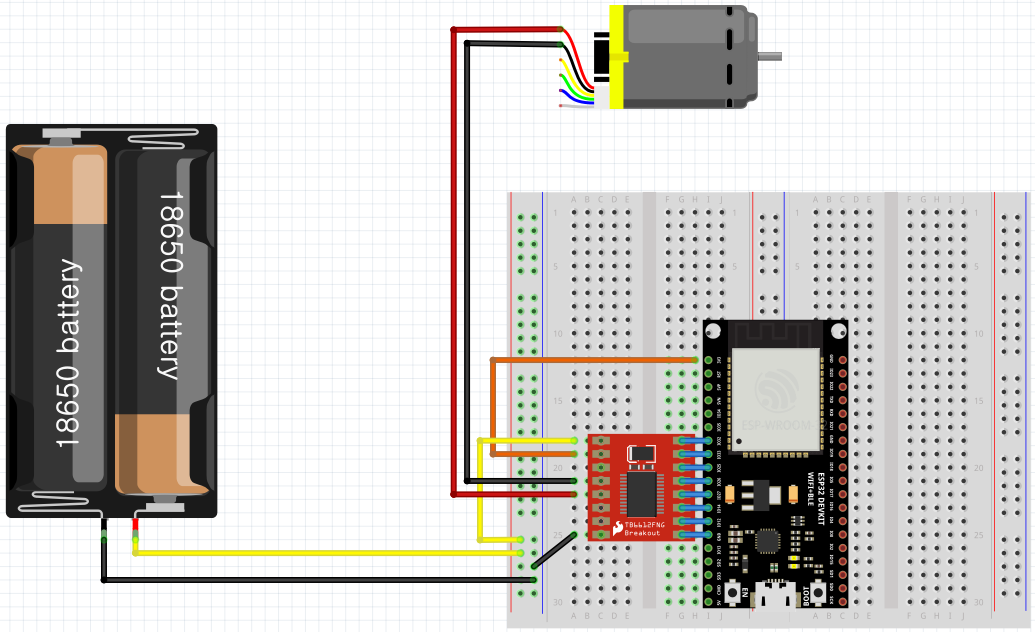
모터 1개 컨트롤하기#
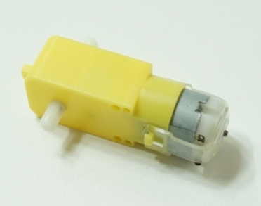
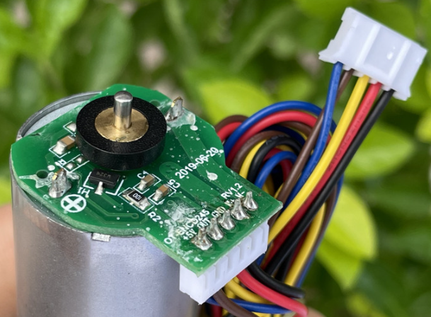
| (기어박스를 포함한) 일반 DC모터 | (엔코더 모듈을 포함한) 엔코더 DC모터 |
|---|---|
| 아두이노를 사용한 스마트카 실습용으로 많이 사용됨 | Hall sensor를 통해 회전수를 정밀하게 측정가능 |
| (+)와 (-), 2P 단자가 있음 | 5P or 6P 단자가 있음 (여기서는 (+)와 (-) 2P만 사용) |
 |  |
schematic#
ESP32와 컴퓨터를 USB선으로 연결하여 사용할 경우 (단, 모터 외부전원은 사용)#
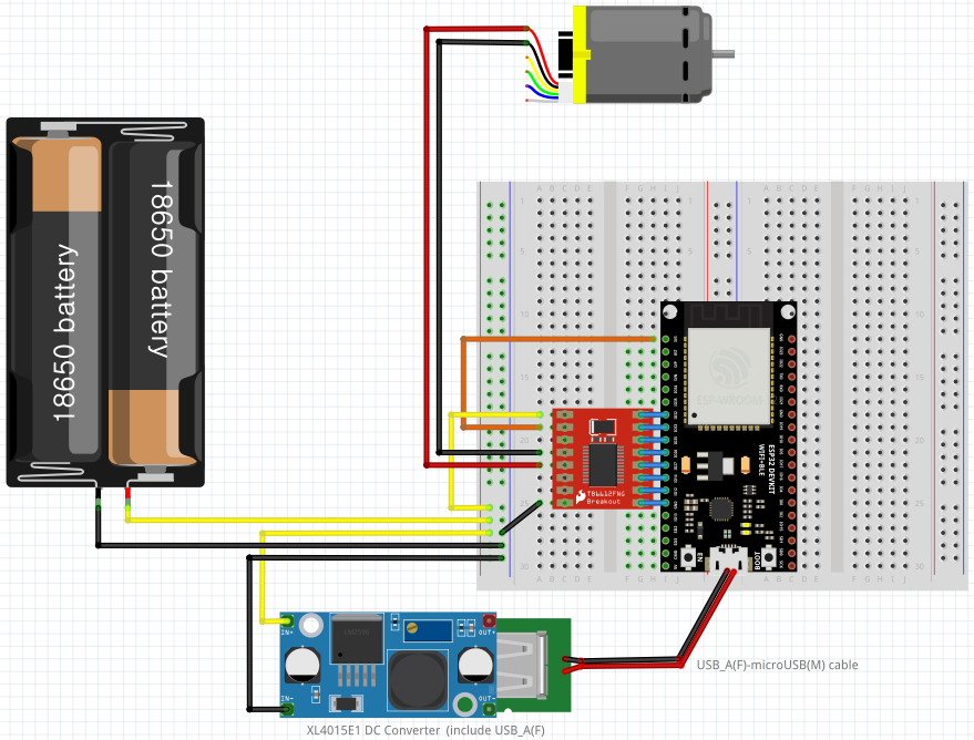
ESP32와 컴퓨터의 연결없이, 외부전원을 사용하여 단독으로 사용할 경우#
18650 2S 외부전원(7.4V)을 DC컨버터 모듈에 연결
- 입력: 8~36V
- 출력: 1.25~32V 및 USB 5V 출력
- 75W내 사용 권장, 전류량 최대 5A (4.5A 이내 사용 권장)
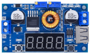
여기서는 서보모터 추가 연결을 위해서, 왼쪽 가변 저항을 사용하여 출력 전압을 5V로 세팅하여 사용
USB 출력단자는 ESP32의 microUSB 단자에 연결
sketch#
// TB6612FNG right side & ESP32-WROOM-32D DEVKIT_C V4 left side pin order
const int PIN_PWMA = 32;
const int PIN_AIN1 = 33;
const int PIN_AIN2 = 25;
const int PIN_STBY = 26;
const int PIN_BIN1 = 27;
const int PIN_BIN2 = 14;
const int PIN_PWMB = 12;

/*
// TB6612FNG right side & ESP32-WROOM-32 left side pin order
const int PIN_PWMA = 33;
const int PIN_AIN1 = 25;
const int PIN_AIN2 = 26;
const int PIN_STBY = 27;
const int PIN_BIN1 = 14;
const int PIN_BIN2 = 12;
const int PIN_PWMB = 13;
*/

// PWM Channel setup
const int CH_PWMA = 0;
const int CH_PWMB = 1;
// PWM frequency and bit resolution setup
const int pwmFrequency = 10000;  // Hz
const int bitResolution = 8;     // pwm value: 0~255

const int PIN_LED = 2;

void setup() {
  // put your setup code here, to run once:
  Serial.begin(115200);
  pinMode(PIN_LED, OUTPUT);

  // tb6612fng setting
  pinMode(PIN_STBY,OUTPUT);
  pinMode(PIN_AIN1,OUTPUT);
  pinMode(PIN_AIN2,OUTPUT);
  pinMode(PIN_PWMA,OUTPUT);
  pinMode(PIN_BIN1,OUTPUT);
  pinMode(PIN_BIN2,OUTPUT);
  pinMode(PIN_PWMB,OUTPUT);

   // motor output(PWM) setting (channel, frequency, bit)
  ledcSetup(CH_PWMA, pwmFrequency, bitResolution);
  ledcSetup(CH_PWMB, pwmFrequency, bitResolution);
  ledcAttachPin(PIN_PWMA, CH_PWMA);
  ledcAttachPin(PIN_PWMB, CH_PWMB);

  // channel setting (GPIO pin, channel)
  // if STBY(CH0) = LOW, Standby states.
  // if STBY(CH0) = HIGH, and INA1&INA2 have different value
  // and PWMA has some value, CW or CCW rotation is made.

  // Channel      CW   CCW  Stanby Stop Brake1 Brake2 Brake3
  // PIN_STBY (0) HIGH HIGH LOW    HIGH  HIGH  HIGH   HIGH
  // PIN_INA1 (1) HIGH LOW  *      LOW   HIGH  LOW    HIGH
  // PIN_INA2 (2) LOW  HIGH *      LOW   HIGH  HIGH   LOW
  // CH_PWMA  (3) PWM  PWM  *      HIGH  *     LOW    LOW
}

void loop() {

  // Motor A : CW
  digitalWrite(PIN_STBY, HIGH); 	// STBY
  digitalWrite(PIN_AIN1, HIGH); 	// AIN1
  digitalWrite(PIN_AIN2, LOW);   	// AIN2
  ledcWrite(CH_PWMA, 255); 			// PWMA
  // Motor B : CW
  digitalWrite(PIN_BIN1, HIGH); 	// BIN1
  digitalWrite(PIN_BIN2, LOW);   	// BIN2
  ledcWrite(CH_PWMB, 255); 			// PWMB
  delay(3000);

  // Motor : Stand-by
  digitalWrite(PIN_STBY, LOW); 		// STBY
  //delay(1000);

  //LED Blink
  digitalWrite(ledPin, LOW);
  delay(3500);
  digitalWrite(ledPin, HIGH);
  delay(500);
  digitalWrite(ledPin, LOW);

  // Motor A : CCW
  digitalWrite(PIN_STBY, HIGH); 	// STBY
  digitalWrite(PIN_AIN1, LOW); 		// AIN1
  digitalWrite(PIN_AIN2, HIGH);   	// AIN2
  ledcWrite(CH_PWMA, 255); 			// PWMA
  // Motor B : CCW
  digitalWrite(PIN_BIN1, LOW); 		// BIN1
  digitalWrite(PIN_BIN2, HIGH);   	// BIN2
  ledcWrite(CH_PWMB, 255); 			// PWMB
  delay(3000);

  // Motor : Stand-by
  digitalWrite(PIN_STBY, LOW); 		// STBY
  //delay(1000);

  //LED Blink
  digitalWrite(PIN_LED, LOW);
  delay(3500);
  digitalWrite(PIN_LED, HIGH);
  delay(500);
  digitalWrite(PIN_LED, LOW);
}Troubleshooting#
스케치 중간에 있는 stand-by가 있거나 없거나 동일한 운동을 보일 것 같지만, 실제로는 완전히 다르다.#
stand-by가 있는 경우
- 3초간 CW회전 후 정지 → 3.5초 대기 → 0.5초 LED켜졌다가 꺼짐 → 3초간 CCW회전 후 정지→ 3.5초 대기 → 0.5초 LED켜졌다가 꺼짐
stand-by가 없는 경우:
- 모터
- 모터의 delay 시간(회전시간)이 3초로 되어 있어도 stand-by 상태로 들어가지 않으므로, 실제로는 7초간 회전 후 방향을 바꿈
- 7초간 CW회전 후 → (정지하지 않고) 곧바로 7초간 CCW회전 (반복)
- LED
- 꺼짐: 6.5초간 꺼져있다가 (모터의 delay 시간 3초 + led low delay 시간 3.5초)
- 켜짐: 0.5초간 켜짐 (반복)
- 모터
그러므로, 각 상황에 따라 stand-by를 걸어야 할지, 말아야할지를 결정해야 함.
- stand-by를 걸지 않은 상태에서 멈추려면 PWMA or PWMB를 0으로 주면 됨.
회전 방향이 (생각했던 방향과) 반대로 회전하는 경우#
AIN1핀과 AIN2 핀의 번호를 바꿔준다. 즉, 위 스케치에서
const int AIN2 = 25;
const int AIN1 = 26;
부분을
const int AIN2 = 26;
const int AIN1 = 25;
로 바꿔준다.
모터 2개 컨트롤하기#
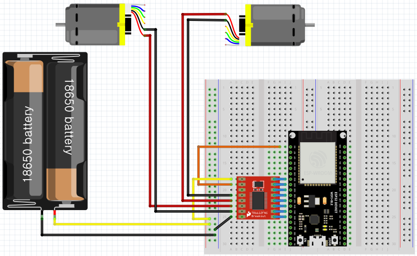
sketch#
위의 ‘‘모터 1개 컨트롤하기’’ 스케치와 동일함.
스케치 최적화#
move(), stop()을 만들어서 스케치 최적화
// TB6612FNG right side & ESP32-WROOM-32D DEVKIT_C V4 left side pin order
const int PIN_PWMA = 32;
const int PIN_AIN1 = 33;
const int PIN_AIN2 = 25;
const int PIN_STBY = 26;
const int PIN_BIN1 = 27;
const int PIN_BIN2 = 14;
const int PIN_PWMB = 12;

/*
// TB6612FNG right side & ESP32-WROOM-32 left side pin order
const int PIN_PWMA = 33;
const int PIN_AIN1 = 25;
const int PIN_AIN2 = 26;
const int PIN_STBY = 27;
const int PIN_BIN1 = 14;
const int PIN_BIN2 = 12;
const int PIN_PWMB = 13;
*/

// PWM Channel setup
const int CH_PWMA = 0;
const int CH_PWMB = 1;
// PWM frequency and bit resolution setup
const int pwmFrequency = 10000;  // Hz
const int bitResolution = 8;     // pwm value: 0~255

const int PIN_LED = 2;


void setup() {
  // put your setup code here, to run once:
  Serial.begin(115200);
  pinMode(PIN_LED, OUTPUT);

  // tb6612fng setting
  pinMode(PIN_STBY,OUTPUT);
  pinMode(PIN_AIN1,OUTPUT);
  pinMode(PIN_AIN2,OUTPUT);
  pinMode(PIN_PWMA,OUTPUT);
  pinMode(PIN_BIN1,OUTPUT);
  pinMode(PIN_BIN2,OUTPUT);
  pinMode(PIN_PWMB,OUTPUT);

   // motor output(PWM) setting (channel, frequency, bit)
  ledcSetup(CH_PWMA, pwmFrequency, bitResolution);
  ledcSetup(CH_PWMB, pwmFrequency, bitResolution);
  ledcAttachPin(PIN_PWMA, CH_PWMA);
  ledcAttachPin(PIN_PWMB, CH_PWMB);

  // channel setting (GPIO pin, channel)
  // if STBY(CH0) = LOW, Standby states.
  // if STBY(CH0) = HIGH, and INA1&INA2 have different value
  // and PWMA has some value, CW or CCW rotation is made.

  // Channel      CW   CCW  Stanby Stop Brake1 Brake2 Brake3
  // PIN_STBY (0) HIGH HIGH LOW    HIGH  HIGH  HIGH   HIGH
  // PIN_INA1 (1) HIGH LOW  *      LOW   HIGH  LOW    HIGH
  // PIN_INA2 (2) LOW  HIGH *      LOW   HIGH  HIGH   LOW
  // CH_PWMA  (3) PWM  PWM  *      HIGH  *     LOW    LOW
}


void loop() {

  move(1, 128, 0);               // motor A(right wheels), half speed, moving forward
  move(2, 255, 0);               // motor B(left wheels), full speed, moving forward
  delay(3000);

  stop();						 // Motor : Stand-by
  //delay(1000);

  //LED Blink
  digitalWrite(ledPin, LOW);
  delay(3500);
  digitalWrite(ledPin, HIGH);
  delay(500);
  digitalWrite(ledPin, LOW);

  move(1, 255, 1);               // motor A(right wheels), full speed, moving backward
  move(2, 128, 1);               // motor B(left wheels), half speed, moving backward
  delay(3000);

  stop();						 // Motor : Stand-by
  //delay(1000);

  //LED Blink
  digitalWrite(ledPin, LOW);
  delay(3500);
  digitalWrite(ledPin, HIGH);
  delay(500);
  digitalWrite(ledPin, LOW);
}

void move(int motor, int speed, int direction) {   //Move specific motor at speed and direction
//motor: A(Right) -> 1, B(Left) -> 2
//speed: 0 is off, and 255 is full speed
//direction: 0 clockwise, 1 counter-clockwise

  digitalWrite(PIN_STBY, HIGH);         // move

  boolean inPin1 = HIGH;            	// Defalut(direction=0) - Clockwise
  boolean inPin2 = LOW;

  if(direction == 1) {             		// Count-clockwise
    inPin1 = LOW;
    inPin2 = HIGH;
  }

  if(motor == 1){                 		// if motor == 1, right wheel
    digitalWrite(PIN_AIN1, inPin1);
    digitalWrite(PIN_AIN2, inPin2);
    ledcWrite(CH_PWMA, speed);
  } else {                         		// if motor is not 1, left wheel
    digitalWrite(PIN_BIN1, inPin1);
    digitalWrite(PIN_BIN2, inPin2);
    ledcWrite(CH_PWMB, speed);
  }
}

void stop() {
  digitalWrite(PIN_STBY, LOW);          // stand-by = stop
}